
Temperature
Temperature data is commonly collected in embedded systems. Many times it’s important to know the temperature of the surrounding environment, especially with outdoor systems. Sometimes, sensors need to be temperature corrected. Monitoring temperature within an electronics enclosure can indicate the health of the electronics. Chances are you will need to include temperature in your next design.
This tutorial will show you how to connect the Analog Devices TMP36 solid state temperature sensor to an Electric Imp, along with the necessary firmware to report the results in Fahrenheit and Centigrade. The TMP36 comes in several packages for both surface mount and through hole fans. We will demonstrate both.
The TMP36 is about the simplest way to gather temperature data. This part features very low quiescent current for minimal impact on system power load. It also has a flexible supply voltage range of 2.7V to 5.5V, which works nicely with the Imp’s 3.3V voltage requirement. The output voltage of the TMP36 also fits within the analog input voltage range of the Electric Imp. It doesn’t get much easier to add temperature measurement capability to your system.
Finished Project
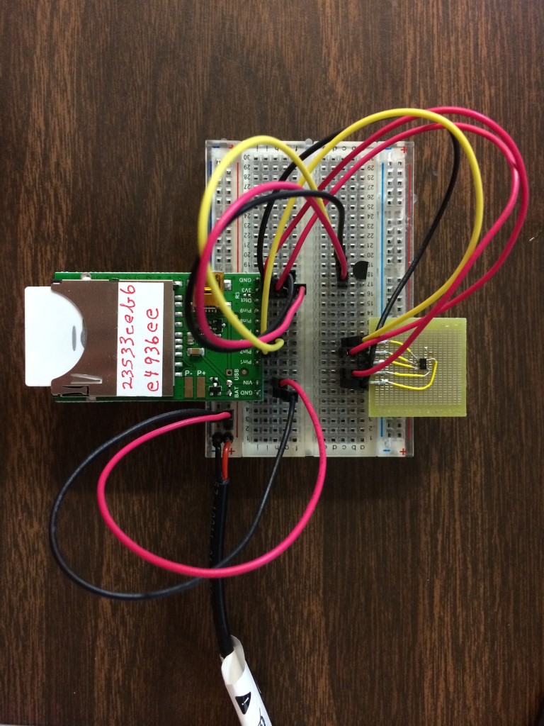
Above is a quick view of what we are working toward, and gives you an idea of the parts needed for this project. The Electric Imp board is at the top of the breadboard, and two variations of the TMP36 temperature sensor are on the bottom half of the breadboard. It will all be explained in detail below.
What you Need
Electric Imp Skill Level
This tutorial assumes that you have basic experience with the Electric Imp. The fine folks at Electric Imp have a “Getting Started” tutorial that will get you going at: http://electricimp.com/docs/gettingstarted. It will explain how to “blink-up” your Imp to connect it to your local network and basics on how to use the Integrated Development Environment (IDE) to enter your code.
Electric Imp
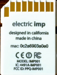
The first thing you will need is an Electric Imp card. It has the same form factor as an SD card, but it is not an SD card in terms of function. You can pick up these cards from any one of several distributers.
Below are two sources for the Electric Imp card.
http://www.digikey.com/product-detail/en/IMP001-US-B/1413-1002-ND/3979639
https://www.sparkfun.com/products/11395

April Card
The April Card is a bare-bones Electric Imp support card that will get you up and running fast. It has a socket for the SD card form factor used by the Electric Imp, some options for supplying power and pin-outs for a header that can allow the card to be mounted on the breadboard.
Below are two sources for the Electric Imp April card.
https://www.sparkfun.com/products/11400

Power Supply
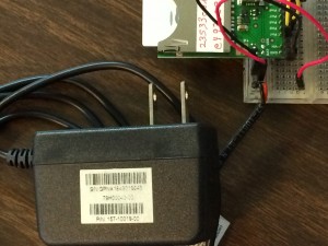
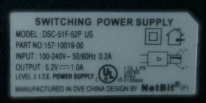
There are a couple of options for supplying power to our project. The April card can be powered from a USB connector attached to a computer, or from a “wall wart” left over from old cell phones. Look at the label, and if it the output voltage is anywhere in the 5V DC range, it should work fine.
TMP36 SMT
This project features two variations of the TMP36: surface mount (SMT) and through-hole. The first part is the SMT version. The data sheet covers both variations: http://www.analog.com/static/imported-files/data_sheets/TMP35_36_37.pdf.
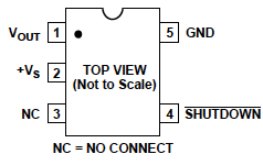
The picture below shows the pin-out of the SMT version. You can purchase the part from the following vendor link.
http://www.digikey.com/product-detail/en/TMP36GRTZ-REEL7/TMP36GRTZ-REEL7CT-ND/1140633
TMP36 T-3
This is the through-hole version of the TMP36. The data sheet is the same as the SMT version above: http://www.analog.com/static/imported-files/data_sheets/TMP35_36_37.pdf.
Below are two sources for the part.
http://www.digikey.com/product-detail/en/TMP36GT9Z/TMP36GT9Z-ND/820404
https://www.sparkfun.com/products/10988
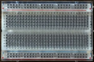
Breadboard
If you do much prototyping, you will need a breadboard. Below are two sources for breadboards.
https://www.sparkfun.com/products/9567
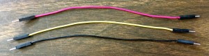
Jumper Wires
There are several options for jumper wires. Below is a source for some easy-to-use male-to-male jumpers.
https://www.sparkfun.com/products/11026
Hardware
In this section, we’re going to build the hardware. The first step is to prepare the Electric Imp and TMP36 for mounting on the breadboard.
Electric Imp April Board
The Electric Imp April board needs to be properly configured for the type of power supply you decide to use. The two options are USB power, or 5V DC power. In our demo, we will use the 5V DC power option, but the USB option setup will be discussed here as well.
First, solder a header across the edge of the board so you can plug it into the breadboard. Make sure the header pins are long enough for the breadboard to grip.
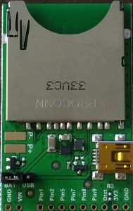
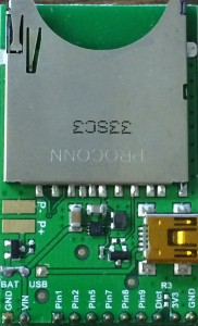
In order to select the power source, we need to place a jumper on the board to make the selection. In the lower left corner you will see three holes with the words “BAT USB” underneath them. Some boards come with a three pin header and jumper in this location.
If you want to supply power from the USB connector, place the jumper on the two USB pins. If you are using a 5V power supply, place the jumper across the BAT pins. You can see this option selected on the board on the left below. The board on the right shows a jumper soldered across the two BAT pins selecting off-board (or battery) power.
For more details on the April board, check the Wiki at: https://electricimp.com/docs/hardware/resources/reference-designs/april/
TMP36 SMT
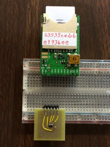
For the surface mount version of the TMP36 we need to adapt it to the breadboard. There are a variety of SMT to through-hole adapters from various vendors. In this example a prototyping system from http://www.boardworxsystem.com is used.
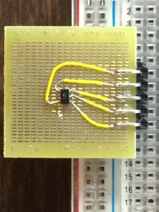
The SMT version of the TMP36 is pretty small, about 3mm x 3mm, including pads. It is a 5 pin SOT-23 package. In the picture above, pins 1 to 5 have been wired to a right angle header in order, starting with pin 1 on the left to pin 5 on the right.
TMP36 Through-hole
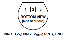
The through-hole version of the TMP36 comes in a three lead package, as seen in the picture below. It can easily be mounted on the breadboard. The pin-out is shown on the right.
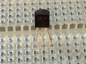
IMPORTANT: The pin-out is shown on the data sheet from the “Bottom View.” If you are looking at the chip from the top, pins 1 and 3 are swapped.
Breadboard
Mount the April card and TMP36 SMT chip on the breadboard.
Wiring
Go ahead and wire up the circuit according to the schematic. It may look like the breadboard in the picture below.
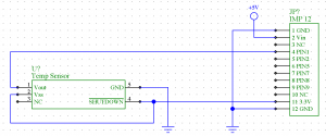
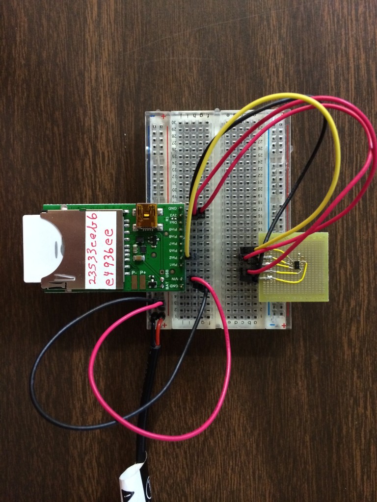
The 5V power is coming in from the wall wart wire on the left, and connects to the breadboard bus bars. Wait just a minute before you plug in the wall wart, or apply USB power. On the TMP36 board, pin 1 starts on the right in the picture.
Power Up
At this point we’re ready to apply power and see what happens. Hopefully, nothing bad will happen, but let’s do a quick check to be sure.
One thing I always do is make sure all the parts are running “cool.” When I first apply power to a circuit I place my finger on parts to make sure that they are not getting hot. If a part is miswired, many times they will get hot very fast. If that happens, turn off the power and check the wiring and voltage polarity carefully before powering again.
The Electric Imp April card is protected against reverse polarity, but it should be checked as well. If the Imp is running properly, you should see the card blink it’s LEDs and connect with your local network.
At this point, you have a working circuit you can test if you want to jump down to the Firmware section. You will be reading from Imp pin 1 and viewing the output on the screen.
Add TMP36 Three Pin Part
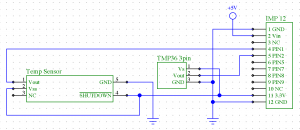

In the schematic and picture above, you can see the addition of the three pin TMP36 part. Go ahead and wire it up.
Power Up
From the previous section, you should have the Imp and TMP36 SMT part running “cool.” Apply power to the circuit with the TMP36 three pin part. Make sure it is not getting hot.
Chances are that you’ve miswired pins 1 and 3. I’ve done it several times because of the way the data sheet labels the pins from the bottom of the part.
Look at the pinout carefully and change the wiring on the board. All you have to do is swap pins 1 and 3. Power the circuit again and make sure it is “cool!”
Firmware
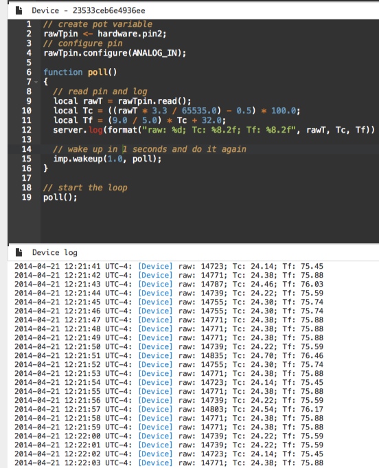
The firmware is simply going to read pin 1 and output the reading data in the log every second. It will look like the screen image below. Note that we are only going to be programming the Device and not the Agent.
You should know how to pick your Imp device and Code Model from the left sidebar. If you need are refresher, check back with the Getting Started tutorial at http://electricimp.com/docs/gettingstarted/2-helloworld/.
The Code
Below is Device code for this tutorial. I suggest that you type the lines rather than simply copying it into the editor. I find that it helps to get used to the editing environment and syntax of the language.
// create pin variable for TMP36
rawTpin <- hardware.pin2; // SMT version
rawT3pin <- hardware.pin5; // 3 pin version
// configure pin
rawTpin.configure(ANALOG_IN); // set pin to analog A/D input
rawT3pin.configure(ANALOG_IN); // set pin to analog A/D input
// poll function will check analog inputs periodically
function poll()
{
// read pin and log
local rawT = rawTpin.read();
local Tc = ((rawT * 3.3 / 65535.0) – 0.5) * 100.0;
local Tf = (9.0 / 5.0) * Tc + 32.0;
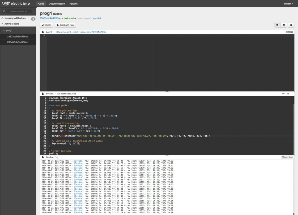
// read 3 pin and log
local rawT3 = rawT3pin.read();
local T3c = ((rawT3 * 3.3 / 65535.0) – 0.5) * 100.0;
local T3f = (9.0 / 5.0) * T3c + 32.0;
server.log(format(“raw: %d; Tc: %8.2f; Tf: %8.2f – raw 3pin: %d, T3c: %8.2f, T3f: %8.2f”, rawT, Tc, Tf, rawT3, T3c, T3f))
// wake up in 1 seconds and do it again
imp.wakeup(1.0, poll);
}
// start the loop
poll();
Try and run it, and see if you get output like the screen shot below.
I hope you enjoyed this tutorial. Keep in touch for more great information from Systems of Merritt, Inc.
Disclaimer
SYSTEMS OF MERRITT, INC. (SOM) MAKES NO OTHER WARRANTIES OR REPRESENTATIONS OF ANY KIND WHATSOEVER, HEREAFTER AND FOREVER, EXPRESSED OR IMPLIED. SOM SHALL NOT BE HELD LIABLE FOR ANY FRUSTRATION OR FUN THAT MAY ARISE FROM THIS TUTORIAL. FURTHERMORE, SOM SHALL ASSUME NO RESPONSIBILITY WHATSOEVER FOR ANY BODILY HARM, HOUSE FIRES, EXPLOSIONS, ACTS OF NATURE, ACTS OF WAR, NUCLEAR EXPLOSIONS OR ANY OTHER EVENT RESULTING FROM THE READING OF THIS TUTORIAL. ONLY INSANE PEOPLE OR LAWYERS EVER READ THIS FAR IN TO DISCLAIMERS. IF YOU ARE ONE OF THOSE PEOPLE, PLEASE BACK AWAY FROM THE COMPUTER, PLACE YOUR HANDS BEHIND YOUR BACK, AND SURRENDER YOUR BRAIN TO SCIENCE.
