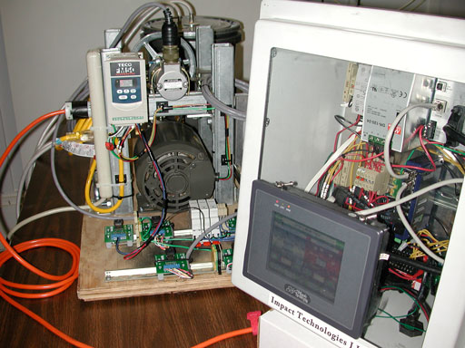
A small mechanical simulator provides an inexpensive means to test software, and even the control loop. The images and discussion below will give you an idea of how Impact Technologies LLC used a desktop mechanical simulator for test purposes.
Impact Technologies LLC had several different types of systems that needed controllers. Rotating systems required rotary encoder velocity feedback. Other systems required pressure feedback, and some required both. In addition to the control aspect, software had to be written to handle other events, such as synchronous valve operation, start-up, shut-down and emergency procedures.
Delta Computer Systems and others make motion controllers which can electronically simulate system responses, but there's no better way to dynamically test live signal interfaces plus a system response than with a mechanical simulator.
In addition to simply controlling motion, motion controllers typically perform additional tasks, such as monitoring signals, and communicating with operator interfaces. As a result, software must be written to handle a number of special conditions, including emergency response situations.
Many emergency situations are too dangerous to test on a live system. The complexity of numerous test conditions make testing on a live system uneconomical, time consuming and inconvenient. It's also a great way to check out new sensor interfaces.

The image above shows the desktop simulator (on left) and the box housing the Delta RMC75E controller and touch-screen operator interface. The RMC75E uses the same signal interfaces on the simulator as it does on the actual system. Those signals include an input system voltage, rotary encoder and pressure feedback.
The power side of the simulator consists of an electric motor and VFD (variable frequency drive). The VFD runs on 110 V, so no special power connections are needed apart from a 110 V outlet. The VFD generates the higher voltages needed to run the motor. The input to the VFD is 0-10 V, which happens to be the same voltage range as a servo valve or linear actuator used on actual systems.
The motor shaft is connected by pully to a linear encoder - the same model of encoder used on actual systems. The motor shaft is directly connected to a small gear pump via a Lovejoy connector. The pump circulates fluid through the container (on left).Antifreeze was used as a fluid to prevent the pump from rusting.
A simple valve was placed on the ouput side of the pump to allow adjustments in flow and pressure. A pressure gauge and transducer were used to monitor pressure both visually and electronically.
A close-up of the pump and motor is shown above. The motor is capable of driving the pump to generate a maximum of about 100 psi. The orange Lovejoy connector allows different shaft sizes to be easily coupled. The valve, pressure gauge and pressure transducer are clearly visible on the output side of the gear pump.
The above image shows the motor and VFD, along with the interface connectors. The optical encoder is mounted above the motor, next to the VFD. On the support on the right is a BEI linear encoder, used to measure distance. The encoder wasn't used for control, but needed to be monitored by the system. The same model of encoder was used on one of the Impact systems.
The simulator was used extensively to test software and control loops for several Impact systems including a 3000 psi hydraulic system and 200 hp diesel engine that were used for various pumping tasks.
The amount of time and money saved by using the mechanical simulator was substantial in terms of reducing test time on the actual systems. The software quality was significantly impacted since many bugs could be tracked down on the simulator system.
Safety was impacted since failure and emergency conditions could be tested on the simulator without creating dangerous conditions on the actual systems. On several occasions, runaway conditions on the actual system were safely shut-down by software tested on the simulator.

![]()
