 Tom Dunlap, President of Tripledee Drilling Company, Inc. in Ardmore, OK invited me to spend the day touring some of his leases and visit with his pumpers about the Smartphone Software project.
It was a beautiful day to be in the field, and the fine folks at Tripledee had lots of great input to the project, and were very patient in answering my questions. At the Oil Expo, the day before, I had the chance to physically look at downhole pumps and have their operation explained to me. The first thing Tom did was give me an overview of the components of the borehole as we stood next to a pump jack.
Seeing the pumping in action gave me a much better understanding of what is needed to keep wells producing in the field. It also further raised the esteem with which I hold the pumpers that tend the wells. The more I learn about well tending, the more I appreciate the skill, hard work, pride and passion these folks have for their work.
 My guide for the day was Dave Fackrell. Dave is the Production Technician for Tripledee and makes sure things are running smoothly. He is also responsible for creating production reports from the field data. After retiring from the Marine Corps, he returned to the oil fields of Oklahoma. He knows the land like the back of his hand and is always looking for ways to improve production.
–
–
–
–
–
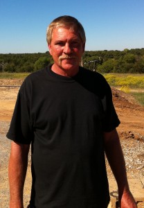 Marty Jones (pictured on right) and his wife Barbara are both pumpers. They joined us at one of the tank batteries and accompanied us to several sites. Marty and Barbara had lots of great suggestions about how the iPhone software could help them on a day-to-day basis.
Purpose of this report
This report is not designed to tell lease owners and pumpers things they already know. The purpose is for Systems of Merritt, Inc. to document and identify elements of the oil field that could use monitoring related to the iPhone software project grant funded by the Stripper Well Consortium.
Readers of this report are encouraged to send comments and ideas to Frank Braswell via phone, email or blog comments.
Site Location
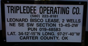 There are so many details to cover, and one of the first things was how to identify the well and its location. Tripledee places the following signs on each well and tank battery for identification.
Two methods of location are on this sign, the latitude and longitude, plus the legal description, which uses congressional townships. It is the line that has: NE SE SW Section 13-4S-2W. You can also see the name of the lease, which in this case is Leonard Bisco. Many states use congressional townships, but interestingly, Texas doesn’t use this location method. My impression is that a latitude-longitude location from the iPhone GPS would be sufficient for most pumpers.
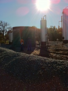 In the tank battery picture on the right various tanks and separator vessels can be seen. The containment berm can be seen in the foreground.
As we visited several wells and tank batteries I began to notice the uniqueness of each installation. Pump jacks were all different sizes and tank batteries varied in the number of separator stages and storage tanks. Some wells produced no gas, while others produced mostly gas and little oil. The water cut varied greatly. Some wells produced huge quantities of water, while others produced higher percentages of oil.
The oil fields of western Pennsylvania that I saw were fairly uniform by comparison. They were relatively shallow and used the same size of pump jacks. Separation was done in one stage.
In Carter County, Oklahoma by contrast, with such wide variations in equipment, even across the same lease, pumpers are challenged with maintaining a wide range of equipment for pumping and fluid handling. That means that measurement requirements vary from site to site. Also, different gauges, seals, fan belts, motors, chemicals, and many other items need to be tracked and replaced as needed.
GPS Location
At one of the tank batteries, we took a GPS location reading. The iPhone 4 had the latitude and longitude within just a few seconds. Using the GPS location we brought up a map on the screen as can be seen below.
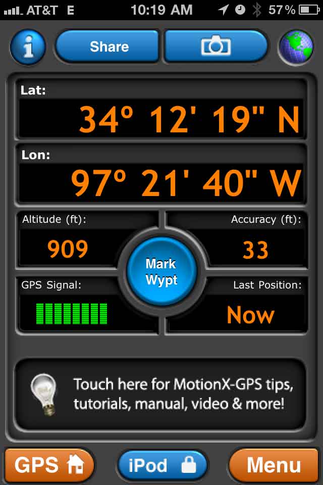
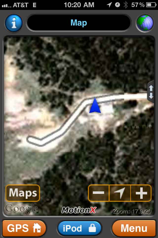
While the GPS location is fairly quick, the maps must be downloaded, which is dependent on the cell signal strength. It may be possible to avoid the delay by pre-downloading the maps.
When looking at the maps, we were able to easily identify the access roads and general landmarks, however trying to locate individual tanks and features of the pumps was beyond the resolution of the maps. We also noticed that the images were not current, so that new tanks or roads installed in recent months were not necessarily on the maps from Google or Bing.
One thing that was brought up was that the GPS location could be used to keep track of the pumper’s location in case of emergency. Many times pumpers work alone and there are numerous hazards in the field. A panic button feature could be added in case of emergency to send a message for help.
Use of iPhone under field conditions
We had some good discussions about using an expensive electronic device in “dirty” oil field conditions. Virtually all pumpers carry cell phones, which would require the same kind of general care.
Protective cases can be purchased to protect against bumps and drops. Work rags are normally carried by pumpers for wiping their hands, which should protect the iPhone from greasy fingers. Unfortunately, there isn’t a practical way to protect the iPhone, or any cell phone from immersion in fluids.
At the Oil Expo, one office manager said she occasionally had to replace pumper’s cell phones, which had become lost, or damaged. She said one cell phone had been run over by a truck, and another had been dropped into an oil tank.
If the pumper considers the iPhone software of great value, like an expensive tool, perhaps they will take care to protect it.
Communication
Transmission of data back to the office from areas that have poor cell reception was discussed. Owners receive data from the field on a regular basis. Some receive it daily and others weekly. Since the pumpers work and live at a distance from the office, reports are generally faxed, and in some cases emailed to the office.
In the case of the iPhone, it has the ability to communicate via the cell signal or a wireless hub. The data on the iPhone is always available for the pumper, and only the most recent data is needed for transmission. If the cell signal is not available, the software can wait until the pumper is in an area that has a signal, and then transmit the data.
I noticed that most of the areas we visited had at least some signal strength. We also discussed the fact that text messaging can be used in weak signal areas, where voice calls tend to be dropped.
Another communication issue has to do with sharing data between iPhones. The data from one pumper’s iPhone may be needed by another pumper, such as a relief pumper. This could be an important feature.
Data at the wellsite
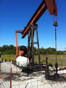 There are a variety of things that pumpers have to check at each wellsite. At the wellhead there is normally a pressure gauge. The polished rod is checked to make sure it is being lubricated adequately and the stuffing box is checked for leaks. The white chemical tank is checked to make sure there is a sufficient supply for the next day.
The stuffing box is shown in more detail in the picture below. The close-up picture of the chemical tank is also shown.
–
–
–
–
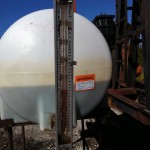
A small amount of chemical is injected into the well with each stroke of the pump. The sight glass gauge in front of the tank is used to monitor the usage of the chemical. A marker on the gauge is adjusted daily and shows the pumper where the level was the day before.
–
–
–
–
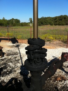 Seals in the stuffing box are constantly monitored for leaks, since they wear out periodically due to friction from the polished rod. The types of seals can vary from well to well.
The pumper also makes note of sounds about the wellsite, listening for any problems with the motor, fanbelt, bearings, gears or pump.
–
–
–
–
–
–
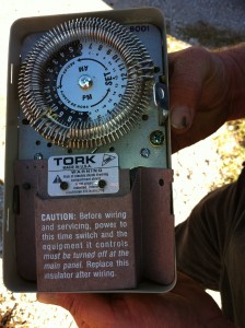 The pumper is also responsible for determining the pumping cycle for each well, in order to produce the most oil. A well can be “programmed” with a timing device, as shown in the image on the right. Over a 24 hour period, the pumper can run the pump at various intervals. It might run 6 hours on and 6 hours off.
Pumpers also conduct tests and inspections on weekly, monthly, semi-annual and annual schedules.
–
–
–
–
–
Data at the Tank Battery
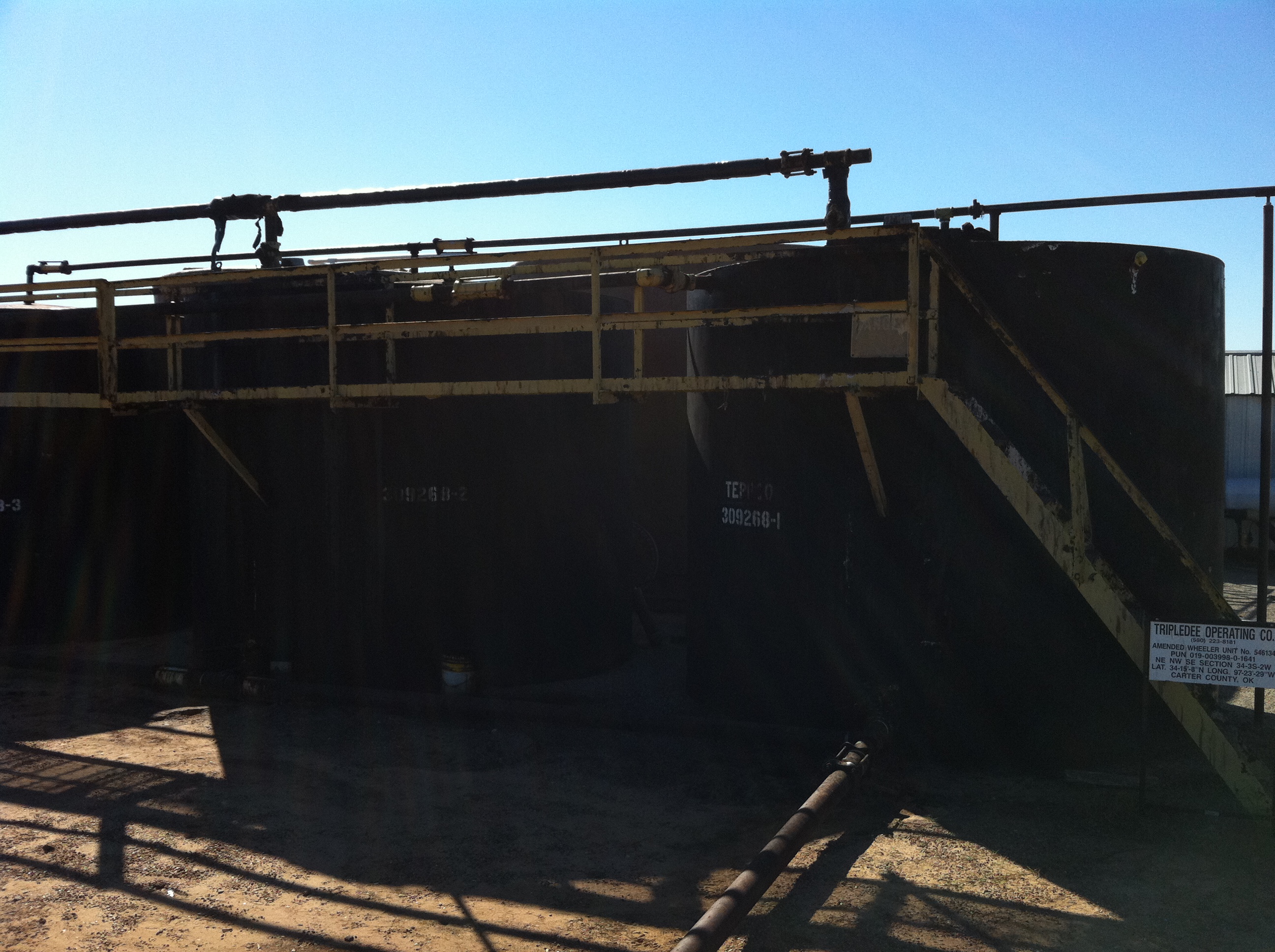 The tank batteries we visited varied considerably in terms of number of tanks, separation vessels and gas production.
Some of the oil needed to be heat-treated in order to separate properly. With each site there are a variety of measurements and gauges that need to be monitored.
Each one of the oil holding tanks is identified by number, so the pumper knows which one is filling, or ready for delivery. The tank that is being filled needs to be monitored daily to determine oil production and also to know when to call for oil pick-up.
–
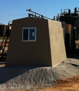
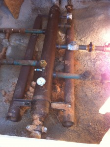 Covering the header assembly, pictured on the right is in a special structure, also shown on the right. The purpose is to maintain the temperature of the fluids from multiple wells as they enter the header. This is especially important in the winter to avoid freezing conditions for the fluids.
–
–
–
 The temperature gauge can be seen mounted on the header. A close-up of the gauge is shown on the right. As can be seen, the gauge indicates the fluid is about 70 degrees Fahrenheit.
–
–
–
–
–
Injection Wells
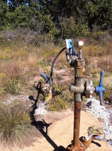 Tripledee also makes use of injection wells, which must be monitored by the pumper. Injection wells can be used for either salt water disposal, or water flooding. Not all leases need injection wells.
A typical injection well is shown on the right. For a water flood, each producing well may have several injection wells spaced around it.
The concept of a water flood injection well is that by forcing fluids into an array of injectors, oil-bearing reservoir fluids will be moved toward the producing well in the same zone.
For fluid disposal, the injection well forces the fluids into non-producing zones.
–
–
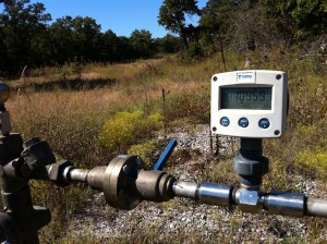 For performance, and also for environmental compliance reasons, each injection well must be monitored. Fluid flow entering the well is monitored by a flow meter shown in the picture on the right. It has a digital display.
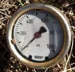
Two pressure measurement are monitored. The incoming pressure is checked, and is controlled by valves at the wellhead.
The casing pressure is also measured. It should read zero under normal conditions, since all of the fluid should be injected directly into the formation. If the casing pressure is greater than zero, the pumper must take corrective measures.
 -
-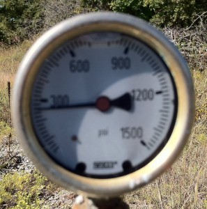
Pictures of both pressure gauges are shown on the right. The injection side for this well reads just under 300 lbs and the annulus pressure gauge reads zero.
–
–
–
Summary
The Tripledee team had lots of great ideas and discussion. Because the pumper needs to cover upwards of 50 wells, it is important to have well and tank data readily available. This includes not only gauge readings, but also things like fan belt sizes, stuffing box seal sizes, and other information specific to each well or tank battery. Additionally, the program could track maintenance and compliance tasks.
The visual nature of the gauge interface, as shown on the right, was well received, and we discussed ways to make it even more usable. There’s no question that field-testing would be needed to make the final determination, but everyone feels this is a good start.
